Blockset described on this wiki is deprecated since 2012.
For Model Based Design (MBD), use the free MPLAB Device Blocks for Simulink, tool from Microchip.
Updated Rapid Control Prototyping (RCP) custom projects are published at: https://lubin.kerhuel.eu.
Difference between revisions of "DsPIC Block/Master"
LubinKerhuel (talk | contribs) |
LubinKerhuel (talk | contribs) |
||
| Line 8: | Line 8: | ||
==Step Based on== | ==Step Based on== | ||
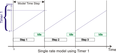
| − | [[Image:TimeStep_SingleRateTimer1.png|thumb|400px|right|Time Step reference is Timer 1. Timer 1 prescaler and PR1 register are configured so as to meet the time step set in Simulink. When Timer 1 reach PR1, it is reset and a next step is started.]] | + | [[Image:TimeStep_SingleRateTimer1.png|thumb|frame|400px|right|Time Step reference is Timer 1. Timer 1 prescaler and PR1 register are configured so as to meet the time step set in Simulink. When Timer 1 reach PR1, it is reset and a next step is started.]] |
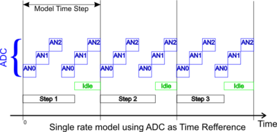
| − | [[Image:TimeStep_SingleRateADC.png|thumb|400px|right|Time Step reference is the ADC peripheral. ADC conversion are slowed down so as to meet the time step requirement set in Simulink. On this example, Three channels are converted ; Two sample are read at each step (i.e. the three ADC blocks output are vectors of 2 elements each).]] | + | [[Image:TimeStep_SingleRateADC.png|thumb|frame|400px|right|Time Step reference is the ADC peripheral. ADC conversion are slowed down so as to meet the time step requirement set in Simulink. On this example, Three channels are converted ; Two sample are read at each step (i.e. the three ADC blocks output are vectors of 2 elements each).]] |
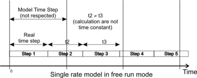
| − | [[Image:TimeStep_SingleRateFreeRun.png|thumb|400px|right|Time Step in Free Run mode. The model is executed as fast as it can. The time step set in Simulink is not respected.]] | + | [[Image:TimeStep_SingleRateFreeRun.png|thumb|frame|400px|right|Time Step in Free Run mode. The model is executed as fast as it can. The time step set in Simulink is not respected.]] |
* Tmer1 : The model time step is set using the Timer1 automatically configured (Prescaler and PR1). | * Tmer1 : The model time step is set using the Timer1 automatically configured (Prescaler and PR1). | ||
Revision as of 22:18, 12 June 2008
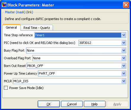
The Master block set important dsPIC options like PLL, Quartz used, and share theses parameters with others blocks from the blockset.
Contents
Dialog Box Parameters
Step Based on
- Tmer1 : The model time step is set using the Timer1 automatically configured (Prescaler and PR1).
- ADC : The ADC conversion time can be used only when the ADC block is set to produce two or more sample per channel. The conversion time is 'augmented' so as to have reach the model time step at the end of all conversion needed in 1 time step.
- Free Run : The model execute at its maximum speed. The Time step is not constant since the calculation time may changed slightly between time step. The simulink model time step is not taken into acount.
PIC
Specify the Microchip microcontroller target.
59 Supported devices :
|
See Release Notes and known bug for details
|
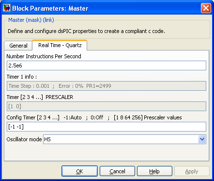
Instruction Cycle Frequency
Specify the Instruction Per Secondes (MIPS) executed not gven in million here. Configuratoin of UART baud, timers prescaler and the time step rely on this frequency information. When using a quartz, the instruction frequency is calculated using : IPS = (FreqQuartz / 4) * PLL factor (1 if no PLL used).
Config Timer
Set the prescaler for the timer 2,3 and 4,5 when available in the microcontrôller. Theses times are used by certain periphery like Output Compare, Input Capture. Set -1 for the timer prescaler to be set by matlab using optimal criterion.
Busy Flag Port
Set the port specified to 1 during the time step calculation and 0 during idle time. This allow to check that all calculation are finished in less that one time step.
Busy Flag Port
Set the port specified to 1 during one time step if the previous time step was not finished when starting the execution of current time step.
config Oscillator mode
Sepecify PIC Oscillator configuration.
config Born Out Reset
Specify Voltage under which the microcontrôller Reset.
config Power Time
Specify time for the pic to start onced powered. (Lets time for alimentation tension to settle properly before starting instructions execution).
config MCLR
If disable, MCLR pin has not the hardware reset function on programme execution. When enable, Pic stop execution and reset when MCLR pin is in its low state.

