Blockset described on this wiki is deprecated since 2012.
For Model Based Design (MBD), use the free MPLAB Device Blocks for Simulink, tool from Microchip.
Updated Rapid Control Prototyping (RCP) custom projects are published at: https://lubin.kerhuel.eu.
PIC32 Sensorless Speed Controller for DC Motor Applied on Picooz Main Rotor
Implementation of a sensorless DC speed motor control system with a PIC32 microcontroller.
Contents
Introduction
One common problem of battery powered system is their dependence on the accumulator voltage. In the case of the Picooz tiny helicopter, the speed rates of the main and tail propellers are crucial for precise control. On the original Picooz electronics, it seems that motor are controlled in open loop in the way that the motor's power is proportional to the joystick stick. Thus, as the battery voltage decrease, both motor slow-down and the user have to adjust both sticks in real time. A sensorless speed controller which requires only one ADC input channel allows overcoming that problem. The speed controller will also speed up the dynamic of the motor and will reject efficiently external perturbations.
The objective here is to design a DC motor speed controller without any speed sensor. Motor's rotational speed is estimated by a measurement of the back-Electro Motrice Force (EMF). The motor is commanded through a PWM signal. During the PWM time where the motor is not powered, the motor acts as a dynamo. Measuring the generated voltage provides pretty good speed estimation.
A dsPIC or PIC32 are ideal target to test such controllers. The blockset for simulink available on this website allow implementing the controller efficiently without requiring knowledge about microcontrollers's programming technics.
Electronics
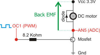
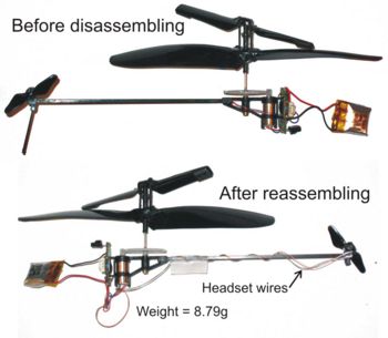
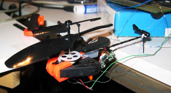
I did not build a complete embedded electronic system for the PICOOZ. This is a demo example is based on the Explorer 16 board, using the PIC32MX460F512L gracefully provided by Microchip. Converting the code for others dsPIC (30f, 33F, 24h) is quite straight using the Simulink blockset. Thus, the Picooz is taken as a test bench for the design of a sensorless speed controller. i.e. The helicopter will not flight in these tests.
One tiny electronics board composed of three components (see image) is connected to the Explorer 16 board. This tiny board allows providing energy power supply to the motor. The motor power supply is controlled through a PWM duty cycle from the microcontroller that controls the voltage given to the motor. The MOSFET transistor: FDC6305N act as a high speed switch. When passing, its internal resistor is only of 0.1 Ohms. This small resistor has small impact on the max speed. It also makes the MOSFET to keep low temperature. The resistor between the Microcontrollers OC1 pin (PWM) and the MOSFET protects the microcontroller. The diode in parallel with the DC motor limits the nasty glitch due to the PWM signal passing through the motor coil. This diode is very important to protect the microcontroller. Removing this diode may severely damage the ADC of the microcontroller, of the entire microcontroller.
Measuring the Back EMF
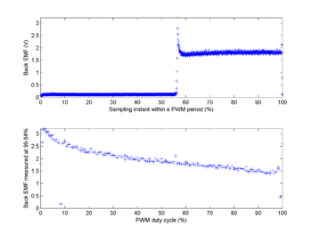
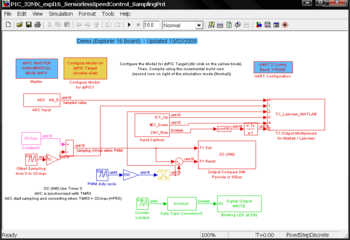
A first simulink model programs the microcontroller so as to set-up the back-EMF measurement. This first model increase linearly the PWM motor duty cycle (from 0 to 11999 with a step size of 100) increasing the PICOOZ rotor's speed rate. There is no feed-back in this first experiment. For each 119 different duty cycle, the ADC channel 5 is sampled at 1200 different places within the PWM period. Thus, we obtain a 2D matrix, with the back EMF measurement (ADC conversion on AN5) in function of both
- The Sampling position within PWM period
- The PWM duty cycle
Theses measurement allows to determine the best place within the PWM period to measure the back EMF, and also allows to see the Back EMF evolution in function of the PWM duty cycle (i.e. in function of the motor speed rate).
Identification of the dynamic of the Picooz's main rotor
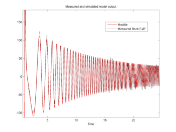
The design of a controller requires a model. A second simulink model programs the microcontroller to test the dynamic response of the motor. The Back EMF is there always sampled at 99.7% of the PWM duty cycle (instant 11970 of 11999, we takes some safety margin). The PWM duty cycle is now a chirp signal (sinus with increasing frequency) that makes the motor to accelerate and to slow down at increasing frequency. We supposed that the Back-EMF is an image of the motor speed rate. Thus, the motor model is identified using the matlab ident graphical user interface.
We get a two poles model for the Back-EMF (i.e. for the motor's dynamic)
[math]G_{motor}(p) = \frac{-24.62}{(p+78.65)(p+9.78)}[/math]
The time constant of the motor [math]\tau_{OpenLoop} = 102ms [/math] is calculated from the slower pole. Let's now design a close-loop controller to improve the motor's response and capacity to reject perturbation (due to gust of wind or to battery power decrease)
Controller design
The controller is designed keeping with theses two constraints:
- The implementation of the PWM output on the OC1 pin is quite sensitive to noisy set point (see blocks page). Thus, the controller command signal should have a reduced noise level.
- The continuous decrease of the battery level act as a continuous perturbation on the controller. Thus, rejecting with no steady states error this perturbation requires at least one integrator within the controller loop.
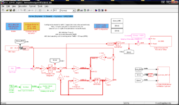
I decided to use an augmented state space model. A state space model has the advantage over a PID or PI only system to filter the output thanks to the internal model. The augmented state is the integral of the error, providing thus a controller with no steady state error.
We use the matlab new command lqi (available from Matlab 2008b) to compute the matrix gain K. The observer gain L is computed so as to get an observer pole as slow as the slowest pole of the close loop control system. Such a low gain allows filtering efficiently noise coming from the PWM measurement.
Ts = .002;  % Controller Sample time

Picooz_Mrotor = zpk([],[-78.68 -9.787],-24.6222);
Picooz_Mrotor_z = c2d(Picooz_Mrotor,Ts,'zoh');
[Picooz_Mrotor_z_ss,T] = canon(Picooz_Mrotor_z,'modal');
      % transformation pour calculs plus simple x ==> T*x

[Az,Bz,Cz,Dz,Te] = ssdata(Picooz_Mrotor_z_ss);
[m,n] = size(Az);

%% Augmented state space synthesis (K)

R = 1;
Q = diag([1 1 2e6]);
[K,Z,e] = lqi(Picooz_Mrotor_z_ss,Q,R,0);

%Poles en continue :
log(eig(Az))/Ts     % System Natural Poles
log(e)/Ts           % Poles in close loop

PolesControlleur_s = log(e)/Ts ;

%% Observer L Synthesis
poleLent = abs(PolesControlleur_s(1:end-1))
PlacementPolesObs = exp(-poleLent * Ts * 1 );  %*3 usually

L = acker(Az',Cz',PlacementPolesObs');

%% Simplification
% Az is diagonal (thanks to the cannon command)
Az = diag(Az)';
We get results for L and K : L = [-0.0593 0.826] and K = [0.5 1.2 1363.9]. With this design, the new motor time constant is The time constant of the motor [math]\tau_{CloseLoop} =70ms [/math]. Thus a 30% improvement. This improvement is not very huge. We are limited here by the necessity to have a low noise command signal. However, the close loop will counteract for the battery decreasing power.
Results


Download
SensorLess_Speed_Controller_ForPicooz.zip
The zip file contains all matlab files as is.
