Blockset described on this wiki is deprecated since 2012.
For Model Based Design (MBD), use the free MPLAB Device Blocks for Simulink, tool from Microchip.
Updated Rapid Control Prototyping (RCP) custom projects are published at: https://lubin.kerhuel.eu.
DsPIC Block/UART Configuration
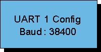
The UART Configuration block set the parameters for the UART. Each UART has one Receive Rx pin and one Transmit pin Tx. The UART parameters are commmon for Rx and Tx of the same UART. The number or UART available depend on the Microcontroller used ( defined in the master block). Following parameters are fixed :
- 1 stop bit
- 8 bits data
- no parity
- no flow control
Related blocks : Block/UART_Configuration Block/Rx_Input Block/Tx_Output Block/Tx_Output_Multiplexed_For_Matlab-Labview Block/Interface_Tx-Matlab
Contents
Dialog Box Parameters
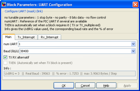
n° UART
UART to be used
Main
Baud (kb/s)
UART Speed you want to use. The exact speed will usually not be reach. An error below 4% usually gives no transmission errors. Check the error speed before use.
Tx Rx Alternativ
Use the Alternative Tx and Rx pin of the microcontroller if available. Use default pin otherwise.
TXEN
Set the output pin TX active for transmitting serial data. This is automatically checked when a Tx or "Tx Output Multiplexed For Matlab Labview" is present.
Info
Gives following information : UxBRG register value. The real bit rate achieved by the microcontroller and the error in percent between the real bit rate and the requested bit rate. The max Byte/Step is the maximum number of byte that can physically be sent during one diagram time step. If your schematic try to send more data through the UART, somme data will not be sent or the real time constraint will be violated (ie, the time step will be longer than expected).
Tx Interrupt
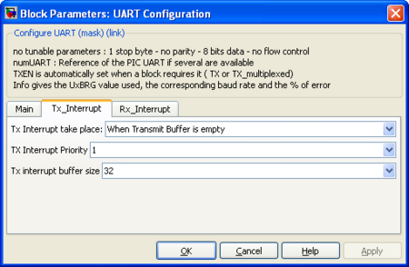
Tx Interrupt take place
The UART peripheral has an internal 4 bytes Transmit buffer. Activating the Tx interrupt virtually extend this buffer to the desired size. The complete buffer size is the sum of the Tx interrupt buffer size plus the UART buffer size (4). The Tx interrupt can take place :
- When the UART Peripheral Transmit buffer is empty
- When the UART Peripheral Transmit buffer has one empty space
Tx Interrupt Priority
Priority of the interrupt (1 is the lowest priority, 7 is the highest)
Tx Interrupt buffer size
Size of the circular buffer used by the interrupt. The total buffer size for the UART Tx peripheral is then the Tx Interrupt buffer size plus the 4 bytes internal peripheral buffer.
Rx Interrupt
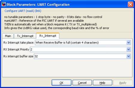
Rx Interrupt take place
The UART peripheral has an internal 4 bytes Receive buffer. Activating the Rx interrupt virtually extend this buffer to the desired size. The complete buffer size is the sum of the Rx interrupt buffer size plus the UART buffer size (4). The Rx interrupt can take place :
- When the UART Peripheral Receive buffer is full (contains 4 bytes)
- When the UART Peripheral Receive buffer is 3/4 full (contains 3 bytes)
- When the UART Peripheral Receive buffer contain 1 byte (receive 1 byte)
Rx Interrupt Priority
Priority of the interrupt (1 is the lowest priority, 7 is the highest)
Rx Interrupt buffer size
Size of the circular buffer used by the interrupt. The total buffer size for the UART Rx peripheral is then the Rx Interrupt buffer size plus the 4 bytes internal peripheral buffer.
<comments \>


