Blockset described on this wiki is deprecated since 2012.
For Model Based Design (MBD), use the free MPLAB Device Blocks for Simulink, tool from Microchip.
Updated Rapid Control Prototyping (RCP) custom projects are published at: https://lubin.kerhuel.eu.
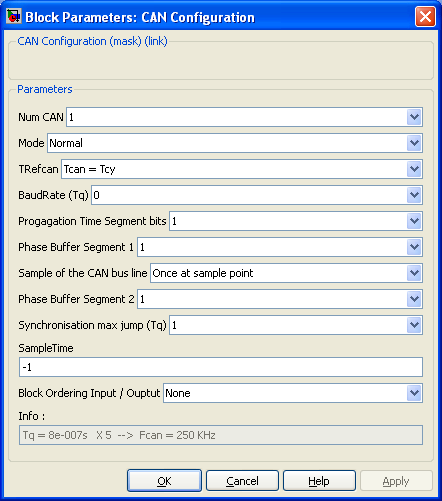
DsPIC Block/CAN Configuration
Configuration for the CAN Peripheral
When using either a CAN Receive block or a CAN Transmit block, this block configure the mode and the CAN BUS parameters.
Contents
Dialog Box Parameters
Num CAN
Ref to the CAN peripheral being configured (some PICs have two CAN buses)
Mode
Configure the mode of the CAN peripheral. Four options are available.
- Normal : the one you will use in most cases.
- Loop back : Allows testing of the CAN peripheral and the CAN blockset. In this mode, no external connection or driver is necessary to make the CAN peripheral work. Messages transmitted are routed directly into the receive logic.
- Listen only : The CAN peripheral receives messages on the bus without transmitting (not even acknowledge bits).
This mode will use only the Receive pin of the CAN peripheral The Transmit pin can be used for another purpose.
- Disable : shut down the CAN peripheral.
These parameters configure the Timing of the CAN bus. Refer to the CAN documentation for more information.
The existing parameter prompts are poor: I have suggested new ones here (the block-set still looks as shown).
- TRefCAN
- Baud Rate Prescaler - 1
- Propagation Time Segment quanta
- Phase Buffer Segment 1
- Times to Sample
- Phase Buffer Segment 2
- Synchronisation max jump (Tq)
The time quanta Tq and the bus frequency Fcan are updated in the Info display each time one of these parameters is modified.
Sample Time
Sample time of the block. -1 for inherited
Block Ordering Input / Output
If you want to force the execution order of blocks that are not connected, this option allow to add either an input, an output or both to the block. These virtual connection allow to force the ordering of the blocks.
Info
Information: the time quantum length Tq and the baud rate of the CAN, given the input oscillator timing TRefCan
Warning
The baud rate is currently incorrectly given for at least the pic30f6014A. It corresponds to 1 more quantum than is actually given to each bit. Reduce one of the segment lengths by 1 quantum temporarily to see the correct baud rate.
In addition, the smallest bit length should be 8 quanta, but the block allows fewer than this to be configured (and shown in the Info display).
I suspect this affects many, if not all, PIC microcontrollers with CAN (rather than ECAN) modules.
see forum related remark: http://www.kerhuel.eu/forum/viewtopic.php?f=8&t=387

