Blockset described on this wiki is deprecated since 2012.
For Model Based Design (MBD), use the free MPLAB Device Blocks for Simulink, tool from Microchip.
Updated Rapid Control Prototyping (RCP) custom projects are published at: https://lubin.kerhuel.eu.
CAN communication between two dsPIC
Contents
Description
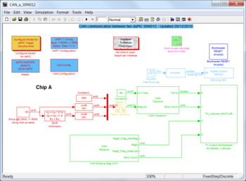
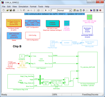
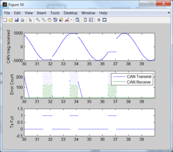
This example shows two dsPIC 30f4012 exchanging data through a bus CAN. The dsPIC embedded program is generated through Simulink and Realtime-Workshop Embedded Coder and the dsPIC blockset. The CAN bus is symmetrical consequently there is no master and no slave. Every 2ms, each dsPIC place one data (frame) on the bus to be read by the other dsPIC. The internal dsPIC CAN peripheral arbitrate bus access to avoid conflict (only one peripheral can write to the bus at one time). Both dsPIC places the received data from the CAN bus to its UART. The dsPIC UART is connected to the PC and the Matlab graphical interface rs232gui allows to plot theses data in real time.
Characteristics of a CAN bus
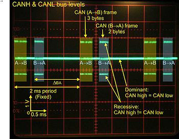
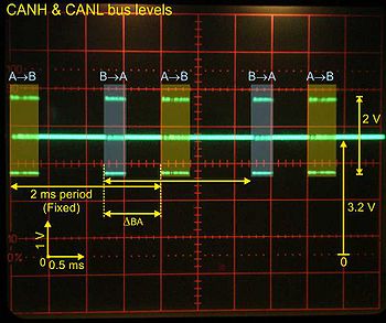
CAN acronym stands for Controller Area Network. It is a numerical bus coding its two states (one dominant and one recessive) using differential voltage between its two wires namely CANH and CANL.
CAN bus is a “multi-slave” bus where any connected dispositive can send a message. Frames are composed of an id which is set by user, and 1 to 8 data bytes. Device waiting for a specific data will filter out incoming frames based on their id. Thus both emitter and receiver exchanging data must have in common the frame id that will be used.
Each CAN frame are acknowledged by the receiver. The message is reemitted by its author until it is acknowledged. However, the reemission is stopped after the xx attempted.
Robust, use in car, error free CRC,
The CAN bus presentation is beyond the scope of this example. Readers are referred to the Wikimedia page on the [1] for further information.
Three blocks related to the CAN bus are available in the dsPIC blockset library.
The CAN Configuration block configure CAN peripheral like bus frequency, time quanta. This block is required as soon as one CAN peripheral is used.
The block CAN Transmit define frame id, data length (1 to 8 bytes) … The block CAN Receive filter out id, set max length of the incoming frame…
Electronics
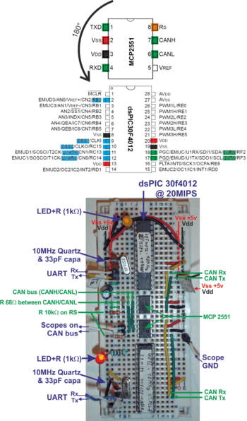
We use the same prototyping board described in the PWM example. And a bootloader capable of flashing the binary into the chip through UART is also used as it is described here.
The PWM wire is removed.
CAN driver description, added components
Simulink models
Two simulink models generate the code for the dsPIC (A) and the dsPIC (B). The common parts of these two models have been described on the PWM example, including the bootloader reset system.
Let’s considers only the specific parts related to the CAN bus of these two models.
Model A: Emission
The model A creates an internal sine wave signal of type int16 with amplitude 5000 and frequency 4 Hz.
Optimized method for sine wave generation was described in the PWM example.

