Blockset described on this wiki is deprecated since 2012.
For Model Based Design (MBD), use the free MPLAB Device Blocks for Simulink, tool from Microchip.
Updated Rapid Control Prototyping (RCP) custom projects are published at: https://lubin.kerhuel.eu.
File list
Jump to navigation
Jump to search
This special page shows all uploaded files.
| Date | Name | Thumbnail | Size | User | Description | Versions |
|---|---|---|---|---|---|---|
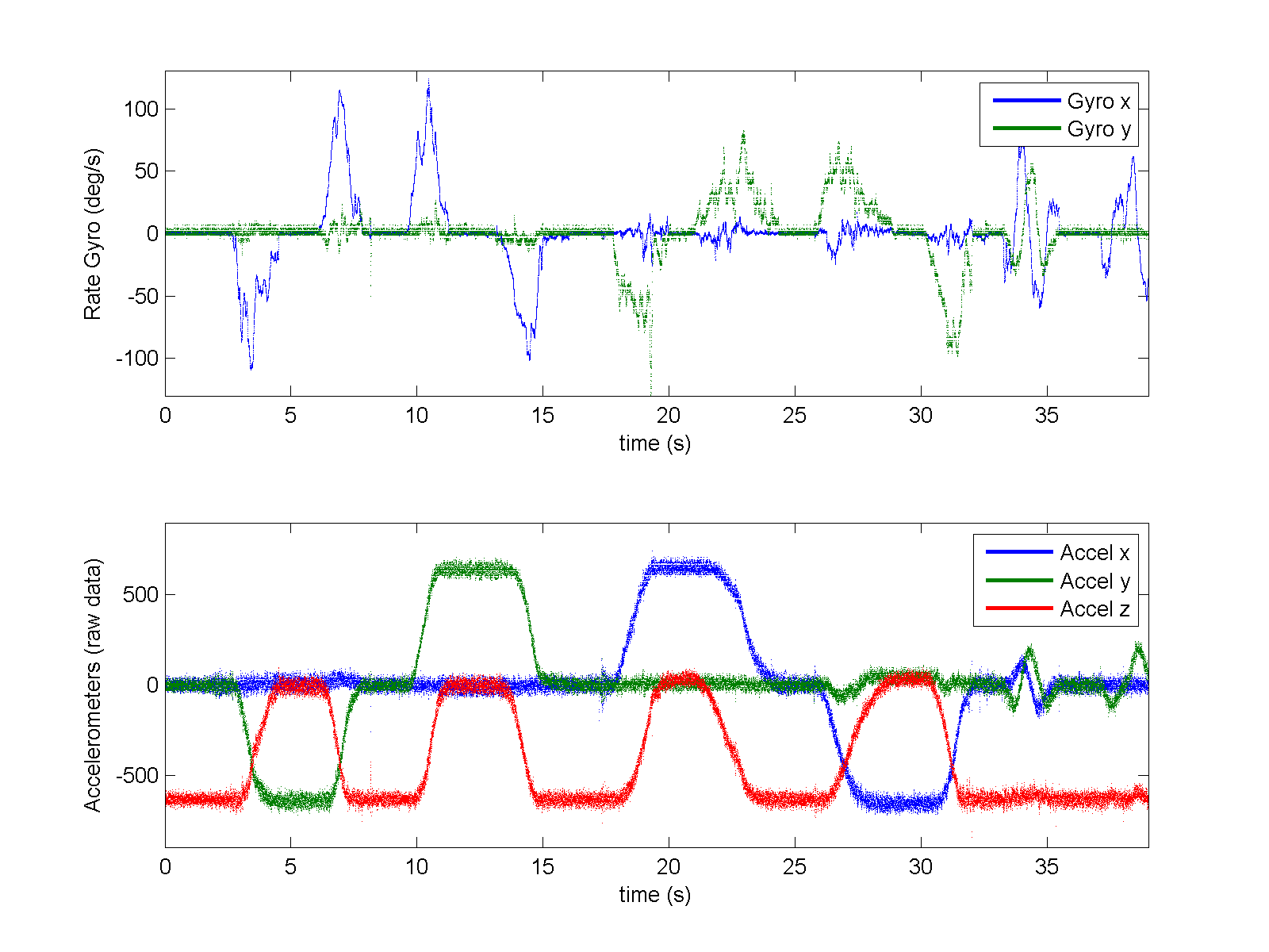
| 19:00, 19 August 2008 | IMU RawData.png (file) |  |
69 KB | LubinKerhuel | top: Raw data from two rate gyro (ADIS 16080). bottom: Raw data from one three axes accelerometers MMA7260. Values from the accelerometers are converted by the gyro 12 bits ADC and sent to the PIC (30f4012) through a SPI bus. | 2 |
| 20:25, 27 July 2008 | Geographylogo.png (file) |  |
2 KB | LubinKerhuel | 1 | |
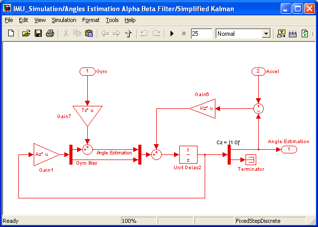
| 13:04, 12 July 2008 | IMU SimplifiedKalman.png (file) |  |
18 KB | LubinKerhuel | The non adaptative Kalman filter track the rate gyro bias and estimate the angle by integrating the unbiased gyro. | 1 |
| 12:43, 12 July 2008 | IMU dsPIC 30f4012 ComplementaryFilter 20Mips.png (file) |  |
32 KB | LubinKerhuel | This model implements the complementary filter on the dsPIC and sends the result to matlab. It has the same behaviors as the simulated filter. | 1 |
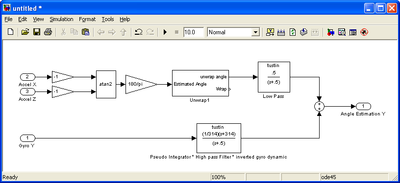
| 12:40, 12 July 2008 | IMU Simulation ComplementaryFilter.png (file) |  |
16 KB | LubinKerhuel | Complementary Filter for IMU angle estimation | 1 |
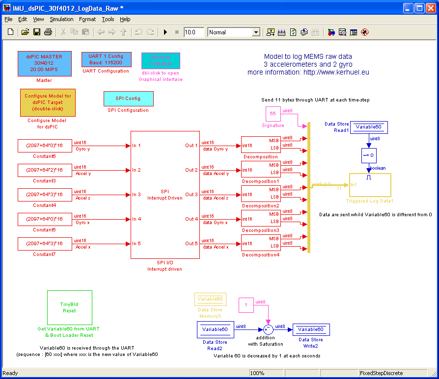
| 12:32, 12 July 2008 | IMU dsPIC 30f4012 LogData Raw.png (file) |  |
35 KB | LubinKerhuel | IMU_dsPIC_30f4012_LogData_Raw Simulink model: Once this model is compiled, the dsPIC (30f4012) transmit the raw values from the MEMs sensors. Data are sent to Matlab (or labview) through the UART at 115200bps with the Tx Output block. The UART buffer do | 1 |
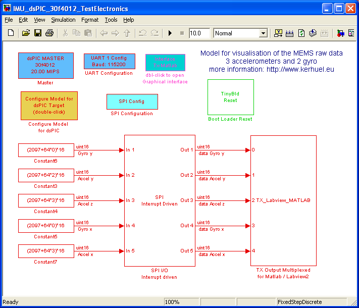
| 12:29, 12 July 2008 | IMU dsPIC 30f4012 TestElectronics.png (file) |  |
26 KB | LubinKerhuel | IMU_dsPIC_30f4012_TestElectronics Simulink model: Once this model is compiled, the dsPIC (30f4012) transmit the values from the X, Y and Z axis of the accelerometer, and the Y and X axis of the rate gyro. Data are sent to Matlab (or labview) through the U | 1 |
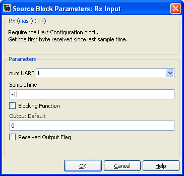
| 07:56, 20 June 2008 | Block UARTRx DialogBox.png (file) |  |
10 KB | LubinKerhuel | 1 | |
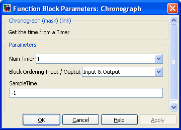
| 21:09, 16 June 2008 | Block Chronograph DialogBox.png (file) |  |
10 KB | LubinKerhuel | 1 | |
| 21:09, 16 June 2008 | Block Chronograph.png (file) |  |
909 bytes | LubinKerhuel | 1 | |
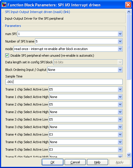
| 21:07, 16 June 2008 | Block SPI IO InterruptDriven DialogBox.png (file) |  |
22 KB | LubinKerhuel | SPI Interrupt Driven Block Dialog Box | 1 |
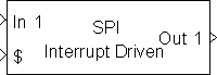
| 21:07, 16 June 2008 | Block SPI Input Output InterruptDriven.png (file) |  |
1 KB | LubinKerhuel | SPI Interrupt Driven Block | 1 |
| 15:36, 15 June 2008 | FlexBoard Blinking Led.mdl (file) | 45 KB | LubinKerhuel | Simulink Model for the Flex Board | 1 | |
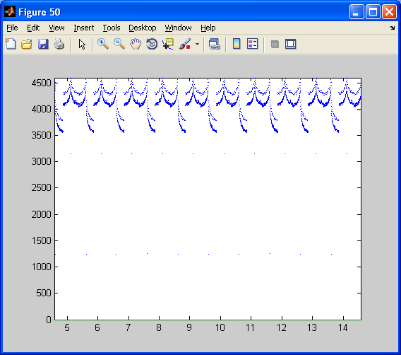
| 15:03, 15 June 2008 | FlexBoard ResultTimeStep.png (file) |  |
15 KB | LubinKerhuel | Time Step. From the Master block, the 2ms time step correspond to a value of 18399. Real time constraints are respected. | 1 |
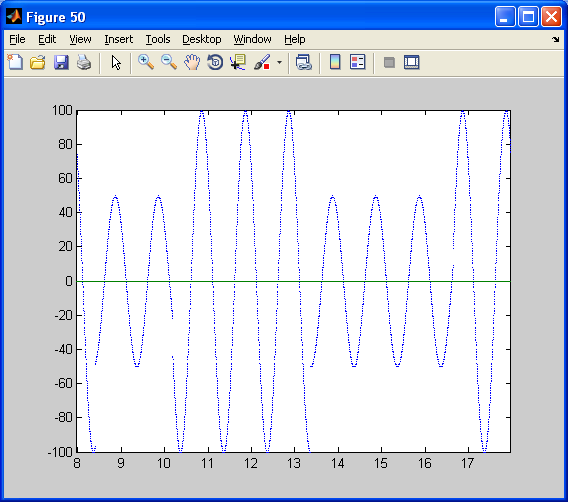
| 15:03, 15 June 2008 | FlexBoard ResultSinus.png (file) |  |
16 KB | LubinKerhuel | Sinus with variable amplitude logged from the Flex Board throught UART | 1 |
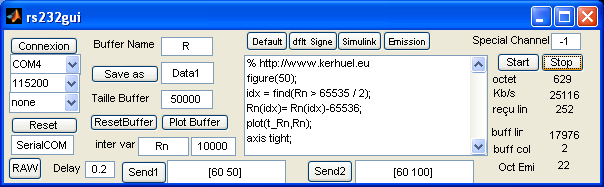
| 15:03, 15 June 2008 | FlexBoard rs232gui BlinkingLed.png (file) |  |
16 KB | LubinKerhuel | Matlab Graphical User Interface to send and log data to and from the Flex Board | 1 |
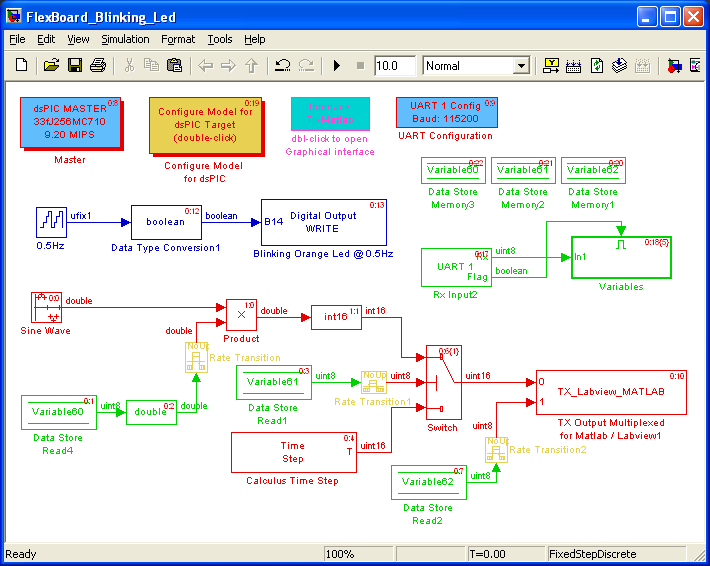
| 15:02, 15 June 2008 | FlexBoard Model BlinkingLed.png (file) |  |
22 KB | LubinKerhuel | Simple Model for the Flex Board | 1 |
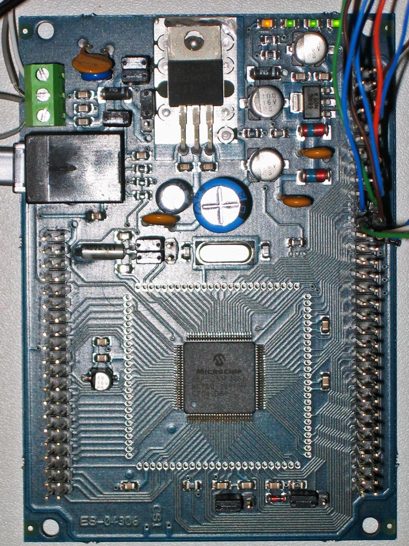
| 15:02, 15 June 2008 | FlexBoard Photo.jpg (file) |  |
296 KB | LubinKerhuel | Flex Board equiped with a dsPIC33Fj256MC710, from Evidence Srl | 1 |
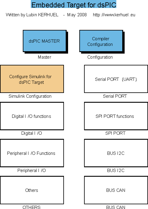
| 10:21, 15 June 2008 | BlocksetLibrary.png (file) |  |
15 KB | LubinKerhuel | PIC/dsPIC blockset Library for Simulink | 1 |
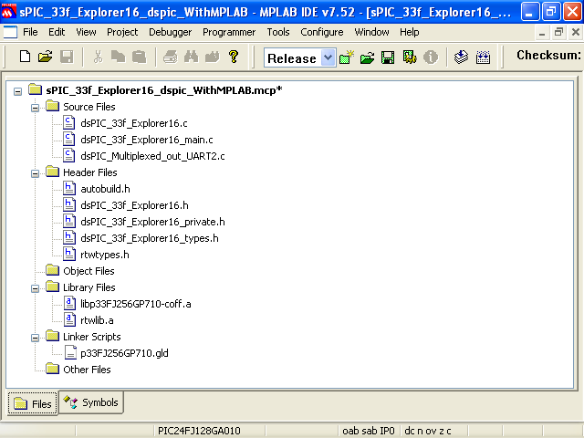
| 18:39, 14 June 2008 | CompilingSimulinkCodeWithMPLAB.png (file) |  |
20 KB | LubinKerhuel | MPLAB project with imported C files and library files (.a) previously generated with simulink | 1 |
| 13:28, 14 June 2008 | Explorer16 LoggedDataCurvesAnimation.gif (file) |  |
148 KB | LubinKerhuel | Animation showing Raw and filtred data (at 1Hz and 10Hz) from the ADC 5 channel connected to the potentiometer | 1 |
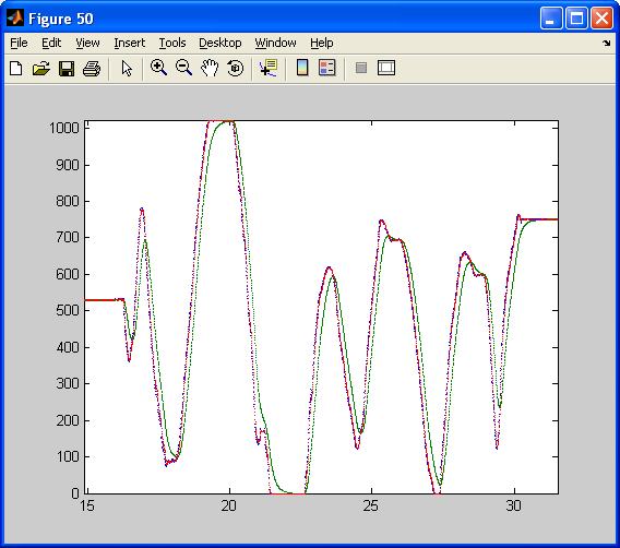
| 13:28, 14 June 2008 | Explorer16 LoggedDataCurvesStatics.png (file) |  |
17 KB | LubinKerhuel | Raw and filtred data (at 1Hz and 10Hz) from the ADC 5 channel connected to the potentiometer | 1 |
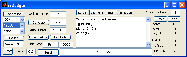
| 13:27, 14 June 2008 | Explorer16 rs232gui.png (file) |  |
15 KB | LubinKerhuel | RS232gui User Interface to log and plot data | 1 |
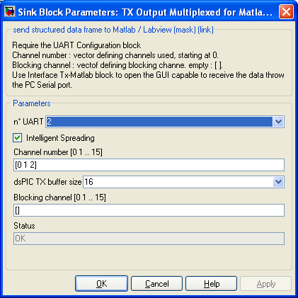
| 13:27, 14 June 2008 | Explorer16 TxMatlabMultiplexed.png (file) |  |
13 KB | LubinKerhuel | 1 | |
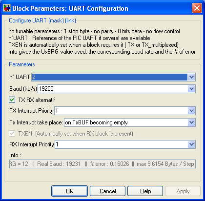
| 13:26, 14 June 2008 | Explorer16 UARTConfiguration.png (file) |  |
14 KB | LubinKerhuel | UART Peripheral Configuration | 1 |
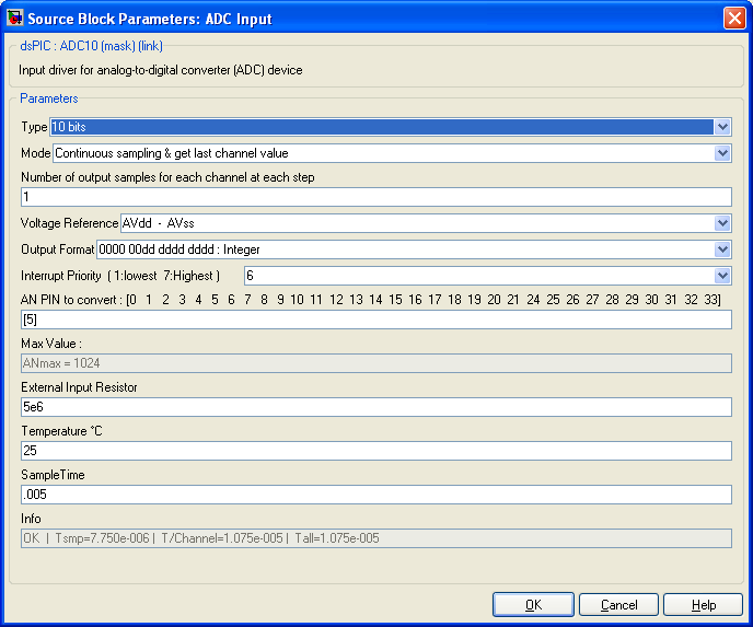
| 13:26, 14 June 2008 | Explorer16 ADCConfiguration.png (file) |  |
16 KB | LubinKerhuel | ADC Configuration | 2 |
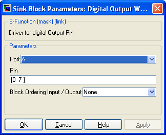
| 13:26, 14 June 2008 | Explorer16 DigitalOutput.png (file) |  |
12 KB | LubinKerhuel | Digital Output Configuration | 1 |
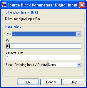
| 13:25, 14 June 2008 | Explorer16 DigitalInput.png (file) |  |
11 KB | LubinKerhuel | 1 | |
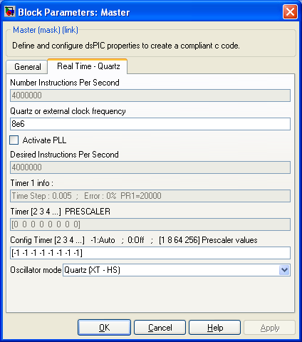
| 13:25, 14 June 2008 | Explorer16 MasterBlockClock.png (file) |  |
15 KB | LubinKerhuel | Master block configuration | 1 |
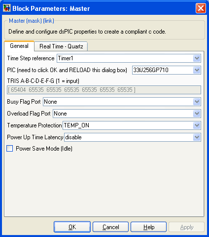
| 13:25, 14 June 2008 | Explorer16 MasterBlockGeneral.png (file) |  |
6 KB | LubinKerhuel | Master block configuration | 1 |
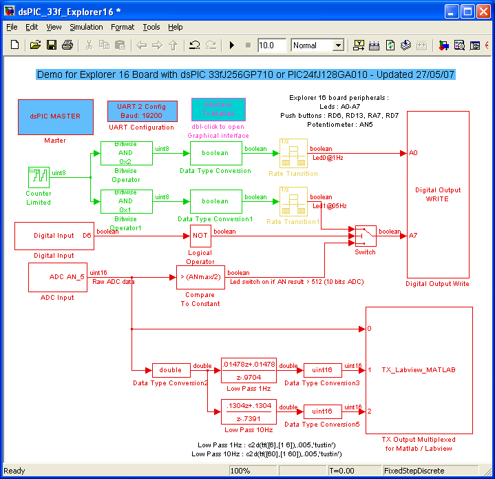
| 13:24, 14 June 2008 | SimulinkExplorer16.png (file) |  |
24 KB | LubinKerhuel | Simulink Model for Explorer 16 Board equipped with 33FJ256GP710 or PIC 24FJ128GA010 | 1 |
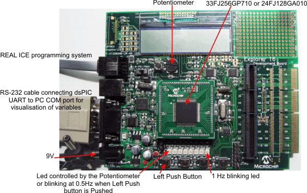
| 13:23, 14 June 2008 | Explorer16Board.png (file) |  |
104 KB | LubinKerhuel | Explorer 16 Development Board equipped with dsPIC 33FJ256GP710 or PIC 24FJ128GA010 | 1 |
| 12:35, 14 June 2008 | LoggingMatlab.swf (file) | 3.26 MB | LubinKerhuel | Flash Animation : Log data sent by the PIC throught the UART Port with Matlab. | 1 | |
| 12:34, 14 June 2008 | Servo Sinus.swf (file) | 1.18 MB | LubinKerhuel | Flash Animation : Compiling a simple model | 1 | |
| 12:22, 14 June 2008 | InstallationProcedure.swf (file) | 313 KB | LubinKerhuel | Flash Animation : Installation procedure for the PIC blockset for Simulink | 1 | |
| 11:16, 14 June 2008 | IMU With dsPIC.zip (file) | 1.03 MB | LubinKerhuel | Models of Complementary Filters implemented on a dsPIC | 1 | |
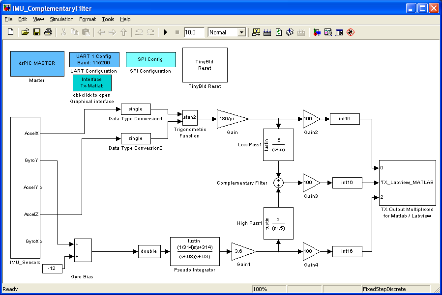
| 21:33, 13 June 2008 | IMU ComplementaryFilter.png (file) |  |
26 KB | LubinKerhuel | The IMU_ComplementaryFilter simulink model is a 'copy-past' mixture made of the IMU_LogData 'data management' part with the IMU_simu_RealData model tuned and optimize filter. This model implement the complementary filter on the dsPIC and send the result t | 1 |
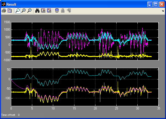
| 21:32, 13 June 2008 | IMU simu RealData Curves.png (file) |  |
25 KB | LubinKerhuel | Top curves : The X (yellow) and Z (cyan) accelerometers raw data with the Y axis rate gyro (pink). The y scale is the raw numerical value as read from the Gyro-SPI bus. The x scale is time (simulation duration is 33,32s). The three bottom curves are the s | 1 |
| 21:32, 13 June 2008 | IMU simu RealData.gif (file) |  |
84 KB | LubinKerhuel | The IMU_ComplementaryFilter simulink model is a 'copy-past' mixture made of the IMU_LogData 'data management' part with the IMU_simu_RealData model tuned and optimize filter. This model implement the complementary filter on the dsPIC and send the result t | 1 |
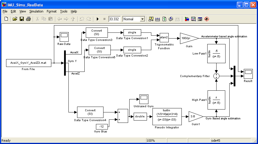
| 21:31, 13 June 2008 | IMU simu RealData.png (file) |  |
23 KB | LubinKerhuel | The IMU_simu_RealData simulink model simulate the complementary filter using the real data previously logged with the dsPIC. Many filters can be tested using the same real data. The frequency of the filter and bias values can be tuned to get the best resu | 1 |
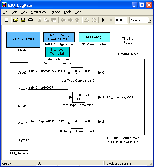
| 21:29, 13 June 2008 | IMU LogDataModel.png (file) |  |
18 KB | LubinKerhuel | Model for Logging data from the IMU sensor board. The dsPIC connected send the sensor's data through its UART peripheral to the computer. Matlab is used to log the data. | 1 |
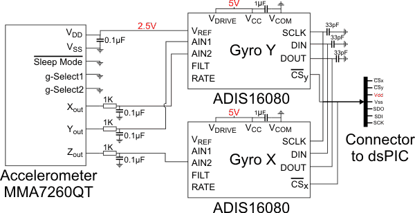
| 21:25, 13 June 2008 | IMU SensorSchematic.png (file) |  |
14 KB | LubinKerhuel | IMU board schematic composed of two gyro ADIS 16080 (analog device) and one accelerometers MMA7260 (freescale). It is connected to the dsPIC through a SPI bus | 1 |
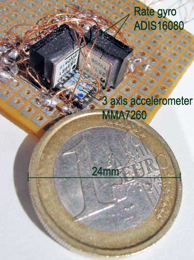
| 02:07, 13 June 2008 | IMU Photo.jpg (file) |  |
76 KB | LubinKerhuel | Photo of the IMU electronic sensors : 1 accelerometer MMA7260 from freescale (3 axis) coupled with 2 gyrometers ADIS16080 from analog device (1 axis each) | 1 |
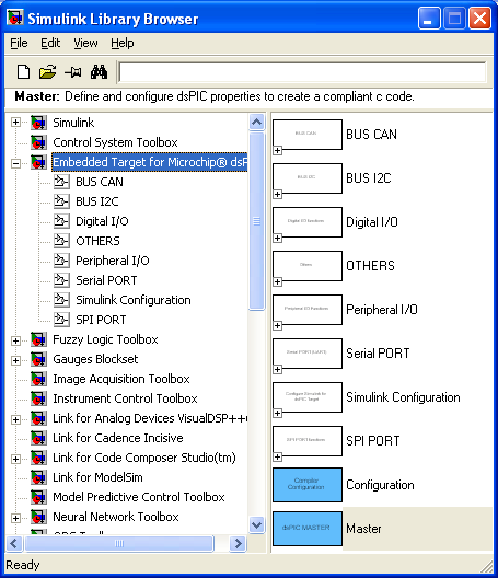
| 21:17, 12 June 2008 | BlocksetLibraryBrowser.png (file) |  |
21 KB | LubinKerhuel | dsPIC blockset for PIC / dsPIC presented in the Simulink Library Browser | 1 |
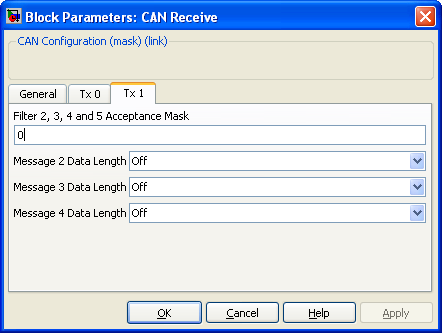
| 19:39, 12 June 2008 | Block CANReceive TabRx1 DialogBox.png (file) |  |
12 KB | LubinKerhuel | 1 | |
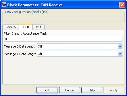
| 19:39, 12 June 2008 | Block CANReceive TabRx0 DialogBox.png (file) |  |
11 KB | LubinKerhuel | 1 | |
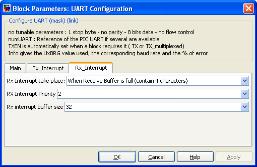
| 19:39, 12 June 2008 | Block UARTRxTab DialogBox.png (file) |  |
14 KB | LubinKerhuel | 1 | |
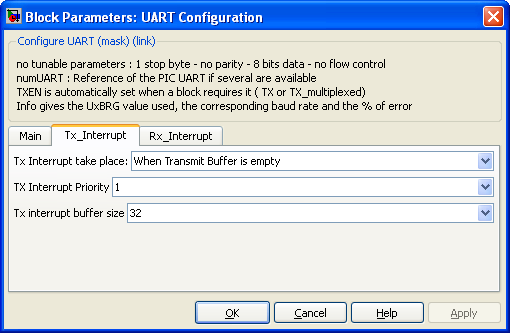
| 19:38, 12 June 2008 | Block UARTTxTab DialogBox.png (file) |  |
14 KB | LubinKerhuel | 1 | |
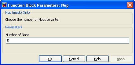
| 19:38, 12 June 2008 | Block Nop DialogBox.png (file) |  |
8 KB | LubinKerhuel | 1 | |
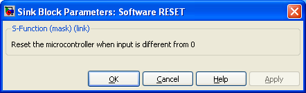
| 19:38, 12 June 2008 | Block Reset DialogBox.png (file) |  |
7 KB | LubinKerhuel | 1 |