Blockset described on this wiki is deprecated since 2012.
For Model Based Design (MBD), use the free MPLAB Device Blocks for Simulink, tool from Microchip.
Updated Rapid Control Prototyping (RCP) custom projects are published at: https://lubin.kerhuel.eu.
Difference between revisions of "Picooz"
LubinKerhuel (talk | contribs) |
LubinKerhuel (talk | contribs) |
||
| Line 7: | Line 7: | ||
=Picooz= | =Picooz= | ||
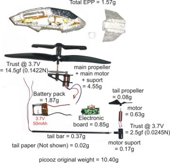
[[Image:Picooz_Inside_Weight.jpg|thumb|right|350px|Inside a Picooz, different part with their respective weight]] | [[Image:Picooz_Inside_Weight.jpg|thumb|right|350px|Inside a Picooz, different part with their respective weight]] | ||
| + | ==Weight== | ||
| + | * EPP : 1.57g | ||
| + | * Main propeller + main rotor + suport : 4.55g | ||
| + | * accumulator : 1.87g | ||
| + | * Electronic board : 0.85g | ||
| + | * tail propeller : 0.08g | ||
| + | * tail motor : 0.63g | ||
| + | * tal motor housing : 0.17g | ||
| + | * tail main bar : 0.37g | ||
| + | * tail paper : 0.02g | ||
| + | * tail thin bar at the end : not measured but very small | ||
| + | * Total (Original Picooz measurement) : 10.40g | ||
==main rotor force== | ==main rotor force== | ||
The picooz helicopter weight '''10.40g'''. It can be '''loaded''' with a '''3.5g''' charge. With a 4g charge, the helicopter takes advantage of the ground effect and can fly, but can't elevate itself in the air. | The picooz helicopter weight '''10.40g'''. It can be '''loaded''' with a '''3.5g''' charge. With a 4g charge, the helicopter takes advantage of the ground effect and can fly, but can't elevate itself in the air. | ||
| Line 32: | Line 44: | ||
The modulation of the IR signal has not been studied. The [http://www.jrl.cs.uni-frankfurt.de/wiki/ProtocolSilverlitIR JRL project] from Goethe University Frankfur provides details about the IR protocol. | The modulation of the IR signal has not been studied. The [http://www.jrl.cs.uni-frankfurt.de/wiki/ProtocolSilverlitIR JRL project] from Goethe University Frankfur provides details about the IR protocol. | ||
| − | |||
| − | |||
| − | |||
| − | |||
| − | |||
| − | |||
| − | |||
| − | |||
| − | |||
| − | |||
| − | |||
| − | |||
| − | |||
=Atlas= | =Atlas= | ||
Revision as of 00:51, 19 January 2009

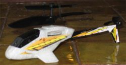
I currently have two helicopters:
- One Picooz
- One Atlas
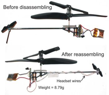
I provide on this page technical measurement from the picooz helicopter. The Atlas model has not been yet opened so less information is presented about it.
Contents
Picooz
Weight
- EPP : 1.57g
- Main propeller + main rotor + suport : 4.55g
- accumulator : 1.87g
- Electronic board : 0.85g
- tail propeller : 0.08g
- tail motor : 0.63g
- tal motor housing : 0.17g
- tail main bar : 0.37g
- tail paper : 0.02g
- tail thin bar at the end : not measured but very small
- Total (Original Picooz measurement) : 10.40g
main rotor force
The picooz helicopter weight 10.40g. It can be loaded with a 3.5g charge. With a 4g charge, the helicopter takes advantage of the ground effect and can fly, but can't elevate itself in the air. The maximum liftoff force given in gram force (gf) is about 14.2gf (139.3 m) (This measurement includes the ground effect). Measurement is difficult to realize as it change over time. At full charge, the maximum liftoff force is attain after few instants (roughly speaking about 40s), time for the motor to warm up. Once wires are warm, their resistance get lower and more energy make it rotates faster.
Tail rotor force
The tail rotor generate a force during fly about 1.40gf (13.7 mN). This force can be modulated with the radio command stick modulated about +- 0.2gf (1.96 mN). When directly connected to the battery, the tail rotor generates a maximum force between 2 and 2.5gf.
Accumulator
The embedded energy is a 3.7V , 50maH LiPo accumulator. When both rotors are at their maximum speed, the voltage drop is about 0.2V, very small compared to the 300 mA drain by the system.
Onboard electronic
The tiny electronic board has two functions :
- controlling the main rotor and the tail propeller.
- demodulating the IR from the remote control
The control of the two propeller is done via PWM signal. For the main rotor, the period of the signal is 8.2ms. For the tail motor, the period of the signal is 17ms. The control of the rotor speed is done by changing the duty cycle duration. These are control directly by the remote control stick. However, the control is not continuous in the sense that several steps can be identified. The control is also not linear as the duty cycle step augmentation get smaller as the full power is approached. In other word, the command is logarithmic. The main motor can be fully powered (i.e. duty cycle = 100%) but the tail motor is never used with a 100% duty cycle.
Two NPN transistors are used to interface the reception part to the power part of the electronic. One NPN 3DA8050M - HY1D transistor is used for each propeller. The electronic can detect (probably using a current measurement) the blocking of the main rotor. The main rotor is blocked for example after a crash. As it happens, both motor are shut down to prevent break because of high current.
The main motor has an internal resistance of 3.20 Ohm. The current measurement in normal operation (with rotor) gives 175 mA. The tail motor has an internal resistance of 7.50 Ohms. The current measurement in normal operation (with the propeller) is about 121 mA. It seems that there is no sensorless speed controller on either of the propeller.
The modulation of the IR signal has not been studied. The JRL project from Goethe University Frankfur provides details about the IR protocol.

