| |
Input-Output Driver for SPI module
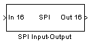
Description
The SPI Input-Output block can be configured as an input for SPI data, as an SPI output, or as both Input-Output. The SPI pin can be disabled after reading or sending data allowing the pin tu be used as a digital output (usefull if weird protocole is used)
Dialog Box
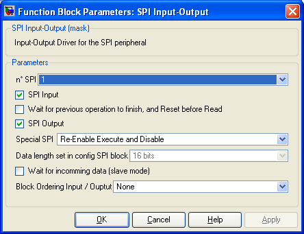
SPI used
-
SPI Input
-
If checked, SPI data will be read This add one output to the Simulink block.
-
Wait for previous operation to finish, and Reset before Read
-
Wait for previous operation to finish, and Reset before Read
-
SPI Output
-
When checked, SPI data will be written to the SPI pin. This add one input to the Simulink block.
-
Special SPI
-
Allow to disable SPI pin function and to use theses pin as digital input/output.
The choices are :
Always Enable
Disable After block execution
Re-Enable before block execution
Re-Enable Execute and disable
-
8 or 16 bits. This option is set in SPI Configuration block
-
Wait for incomming data (slave mode)
-
block execution of other blocks while no data are received
- Block Ordering Input / Output
-
-
Create one input and/or output port on simulink. This port is just used to set the order of execution between severals blocks. You want for example inside one time step set a pin to its high value and to its low value just after (create a glitch). You will used two blocks digital output, but they should be activated in a certain order. Connecting the first block to the second one (temporaly speaking) will allow to respect the execution order you desire.
-
-
Status
-
Provides information like bit rate and status
|
The Microchip name PIC, dsPIC, and MPLAB are
registered trademarks of Microchip Technology Inc.
MATLAB, Simulink, and Real-Time Workshop are
registered trademarks of The MathWorks, Inc.
| Lubin Kerhuel 's Website |
Contact : [adresse e-mail retirée] |
|
|


