| |
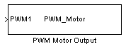
Output driver for PWM Motor
Description
The PWM Motor block allows to generate either simple PWM pulse like OC block or PWM pulse with two channel in opposit phase for motor control. This block do not use a timer like the OC or IC blocks.
Dialog Box
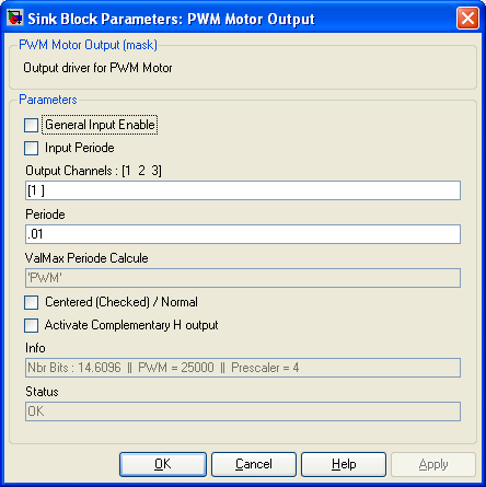
Add the enable input to the block. Allow to Start and Stop the PWM pulses.
-
Input Periode
-
Add the Periode Input. When the PWM periode is not constant, this input allow to control the PWM periode.
-
Output Channel
-
Choose the PWM motor Channels to be used.
-
Periode
-
When Input Periode is disable, Fixed the Periode value.
When Input Periode is enable, This define the max Periode that will be used.
-
ValMax Periode Calcule
-
This Variable will be evaluated in the workspace and allow you to scale the data.The ValMax is the max value that correspond to the duration defined in Periode.
-
Centered
-
I Really do not remember what was that for !
-
Activate H Complementary Output
-
Activate the Complementary output of each channel
-
Info
-
Gives information :
NbrBits is the resolution for the full scale defined by Periode.
PWM max value corresponing to the time defined in Periode. PWM is evaluated in the workspace to allow you to scale the data.
Prescaler is the Prescaler internally used in the microcontroller..
-
Status
-
Information if error encountred.
|
The Microchip name PIC, dsPIC, and MPLAB are
registered trademarks of Microchip Technology Inc.
MATLAB, Simulink, and Real-Time Workshop are
registered trademarks of The MathWorks, Inc.
| Lubin Kerhuel 's Website |
Contact : [adresse e-mail retirée] |
|
|


