| |
Configuration for the CAN Peripheral
Description
When using either a CAN receive block or a CAN Transmit block, this block configure the mode and the CAN BUS parameters.
Dialog Box
-
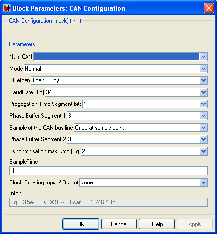
Ref to the CAN peripheral being configured (some PIC have two CAN bus)
-
Configure the mode of the CAN peripheral. Four options are available.
- Normal
The Normal mode is the one you will use in most case.
- Loop back
The loop back mode allow to test the CAN peripheral and the CAN blockset. In this mode, no external connection nor driver are necessary to make the CAN peripheral working. The dsPIC will write and read its own CAN messages.
- Listen only
The Listen only mode make the microcontrolleur able to listen to the can BUS without writting anything. This mode will use only the Transmit PIN of the CAN peripheral The receve PIN can be used for another purpose.
- Disable
The Disable mode shut down the CAN peripheral.
- TRefCAN
BaudRate
Progagation Time Segment bits
Phase Buffer Segment 1
Sample of the CAN bus line
Phase Buffer Segment 2
Synchronisation max jump (Tq)
-
-
Theses parameters configure the Timing of the CAN bus. Refere to the CAN doccumentation for more informations.
The time quanta Tq and the BUS frequency Fcan are updated in the info parameter each time one of these parameters is modified.
-
Sample Time
-
Sample time of the block. -1 for inherited
-
Block Ordering Input / Output
-
If you want to force the execution order of blocks that are not connected, this option allow to add either an input, an output or both to the block. These virtual connection allow to force the ordering of the blocks.
-
Info
-
Information, give the clock frequency Fscl of the I2C bus
|
The Microchip name PIC, dsPIC, and MPLAB are
registered trademarks of Microchip Technology Inc.
MATLAB, Simulink, and Real-Time Workshop are
registered trademarks of The MathWorks, Inc.
| Lubin Kerhuel 's Website |
Contact : [adresse e-mail retirée] |
|
|


