Blockset described on this wiki is deprecated since 2012.
For Model Based Design (MBD), use the free MPLAB Device Blocks for Simulink, tool from Microchip.
Updated Rapid Control Prototyping (RCP) custom projects are published at: https://lubin.kerhuel.eu.
Case Study: Position Control of DC Motor
Contents
Subject:
from the forum (Forum Message):
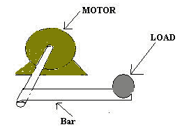
This is one of the first projects I made. I am trying to control a DC servomotor with incremental encoder (FAULHABER 1717V0023). The purpose is place a load on the end of a bar attached to the motor shaft and the motor must keep steadily with no move at all. The motor must stay firm as shown in the drawing attached. So if I change the mass of the load or if I unload the bar, the motor has to stay immobile. This is the model and the C file I am using in a dsPIC30F4012. It seems to work fine, but sometimes when I am pushing or pulling the bar the motor lose control and start running wildly. Can you please tell me if my design is correct, or if I am not considering something important? Why the motor gets crazy?
The left picture shows the original model. (Download the original model and C file on the forum )
Possible problems
controller design
The motor is controlled via PWM signal. As a bidirectional system, the logical pin D0 set the polarity control signal. As the PWM duty cycle is an absolute value, the absolute of the PID is taken as the PWM output control signal. The Directional D0 signal should be the sign of the PID output value. On the current design, Directional D0 signal is taken as the sign of the feedback error. The behaviour will be very different because of the integrator. (For example, if the motor maintain the bar horizontal, the PWM signal will counteract for the gravity effect (thanks to the integrator) But despite the error may change of sign, the polarity of the motor should remain the same.
PID controller
it's better to have anti-windump or at least integrator saturation mechanisms on PID controllers. I am not sure what is done in the built-in PID block. The PID block may be Ok for simulation but I would rather use simple block made PID controller so as to add saturation and reset mechanisms on the integrator.
Overflow
If you encounter problems, set the saturate on integer overflow on all addition or multiplication if you are not sure.
tricks
- Saturation followed by abs
- set the negative saturation at 0 directly


