Blockset described on this wiki is deprecated since 2012.
For Model Based Design (MBD), use the free MPLAB Device Blocks for Simulink, tool from Microchip.
Updated Rapid Control Prototyping (RCP) custom projects are published at: https://lubin.kerhuel.eu.
Flex Board Blinking Led

This example shows how to configure the Flex board for programming using Simulink. It also shows how to send data from the PC to the "onboard Simulink model".
The flex board is a product from the Evidence Srl. It is equipped with a dsPIC 33FJ256MC710. The pin out of the dsPIC is accessible through easy to use connections (HE14 connectors). The overall board is powered with a simple 12V PC alim. Onboard regulator generates the appropriate tension to power up the microcontroller. The board is equipped with a 4Mhz Quartz.
Download the Simulink model: FlexBoard_Blinking_Led.mdl
Model Configuration

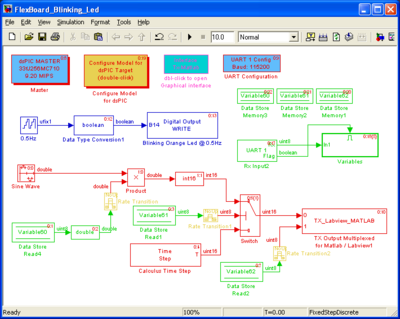
The master block is set up for the dsPIC 33FJ256MC710 with a quartz at 4Mhz.
UART is configured with its maximum speed (for the PC) i.e. 115200 bauds. This UART speed cannot be achieved without enabling the dsPIC clock multiplier PLL. Without PLL, the microcontroller run at 2MIPS and the UART speed error (read from the UART configuration block) is of 8.5%. Therefore, PLL is activated. The targeted speed must be compatible with the UART baud used. With a configuration of 9.2MIPS, UART has a speed error of -0.17% (The real baud is 115000 ; error is : [math]\frac{115000 - 115200}{115200} = -0.0017[/math])
The orange Led of the Flex board is connected to the PIN B14. Therefore, a digital output is set up on B14. Its input is a limited counter with its higher limit set to 1. The counter sampling rate is set to 0.25s (blue colored part of the model). The binary signal generated has therefore a period of 0.5Hz thus the Led blink at 0.5Hz.
Send data from the PC to the dsPIC
The protocol created allows modifying some variables declared at the simulink model while the model is running in the dsPIC. The variable are declared as uint8 with the block data store memory from the standard simulink library. The variables names are Variable60, Variable61 and Variable62.
Changing the value of a variable in the running dsPIC program needs to send two data bytes through the UART. The first byte is the variable reference to be change (it can be 60, 61 or 62). The second byte is the new value of the variable. Thus, the vector [60 50] is set up in the Matlab user interface (rs232gui). Values are sent when the send1 or send2 button is pressed.
On this model (see the model):
- the variable 60 set the amplitude of the sinus generated.
- the variable 61 define which data is send to the PC :
- if 0, the Time Step is being sent
- if 1, the Sinus is being sent.
- the variable 62 is directly sent to the PC
We can see on the figure that the amplitude of the sinus changes as we click on the button send1 or send2 on the matlab user interface.
The max time step recorded for this model is about 4500. With the same scale, the model time step configuration corresponds to 18399. Thus, the dsPIC is used at 25%
[math]\frac{4500}{18399} = 0.25[/math]
It is quite time consuming but this model could be optimized. Generation of the sinus should be done using a look up table (from the simulink standard library) and all calculation should be done using only fixed step variable (no double !)
Thanks to Evidence for providing this Flex Board Light.


