Blockset described on this wiki is deprecated since 2012.
For Model Based Design (MBD), use the free MPLAB Device Blocks for Simulink, tool from Microchip.
Updated Rapid Control Prototyping (RCP) custom projects are published at: https://lubin.kerhuel.eu.
Difference between revisions of "PIC32 Sensorless Speed Controller for DC Motor Applied on Picooz Main Rotor"
LubinKerhuel (talk | contribs) (New page: Implementation of a sensorless DC speed motor control system with a PIC32 microcontroller. =Introduction= One common problem of battery powered system is their dependence on the accumula...) |
LubinKerhuel (talk | contribs) |
||
| Line 9: | Line 9: | ||
A dsPIC or PIC32 are ideal target to test such controllers. The blockset for simulink available on this website allow to implement the controller efficiently without requiring knowlege about microcontrollers's programming technics. | A dsPIC or PIC32 are ideal target to test such controllers. The blockset for simulink available on this website allow to implement the controller efficiently without requiring knowlege about microcontrollers's programming technics. | ||
| − | + | =Electronics= | |
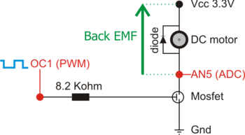
| − | + | [[Image:Picooz_SensorlessSpeedControl_Schematic.png|thumb|right|350px|Electronic schematic connected to an Explorer 16 board. This board power the DC motor with a PMW signal. The PIC OC1 pin generate a PWM signal with controllable duty cycle that control a MOSFET transistor: [http://www.fairchildsemi.com/ds/FD/FDC6305N.pdf FDC6305N]. The back EMF is measured via the AN5 channel of the explorer 16 board. The overall system is powered here at 3.3V but could be powered with higher voltages.]] | |
| + | |||
| + | I did not build a complete embedded electronic system for the PICOOZ. This is a demo example is built on the Explorer 16 board, using the PIC32MX460F512L gracefully provided by Microchip. Converting the code for others dsPIC (30f, 33F, 24h) is quite straight using the Simulink blockset. Thus, the Picooz is taken as a test bench for the design of a sensorless speed controller. i.e. The helicopter will not flight in theses tests. | ||
Revision as of 16:48, 1 May 2009
Implementation of a sensorless DC speed motor control system with a PIC32 microcontroller.
Contents
Introduction
One common problem of battery powered system is their dependence on the accumulator voltage. In the case of the Picooz tiny helicopter, the speed rate of the main and tail propellers are crucial for precise control. On the original Picooz electronics, it seems that motor are controlled in open loop in the way that the motor's power is proportional to the joystick stick. Thus, as the battery voltage decrease, both motor slow down and the user has to adjust both sticks in real time. A sensorless speed controller which requires only one ADC input channel allows to overcome that problem. The speed controller will also speed up the dynamic of the motor and will reject efficiently external perturbations.
The objective here is to design a DC motor speed controller without any speed sensor. Motor's rotational speed is estimated by a measurement of the back-Electro Motrice Force (EMF). The motor is commanded through a PWM signal. During the PWM time where the motor is not powered, the motor acts as a dynamo. Measuring the generated voltage provides a pretty good speed estimation.
A dsPIC or PIC32 are ideal target to test such controllers. The blockset for simulink available on this website allow to implement the controller efficiently without requiring knowlege about microcontrollers's programming technics.
Electronics

I did not build a complete embedded electronic system for the PICOOZ. This is a demo example is built on the Explorer 16 board, using the PIC32MX460F512L gracefully provided by Microchip. Converting the code for others dsPIC (30f, 33F, 24h) is quite straight using the Simulink blockset. Thus, the Picooz is taken as a test bench for the design of a sensorless speed controller. i.e. The helicopter will not flight in theses tests.