Blockset described on this wiki is deprecated since 2012.
For Model Based Design (MBD), use the free MPLAB Device Blocks for Simulink, tool from Microchip.
Updated Rapid Control Prototyping (RCP) custom projects are published at: https://lubin.kerhuel.eu.
File:Bode 1stOrderComplementaryFilter.png
Jump to navigation
Jump to search
No higher resolution available.
Bode_1stOrderComplementaryFilter.png (680 × 597 pixels, file size: 22 KB, MIME type: image/png)
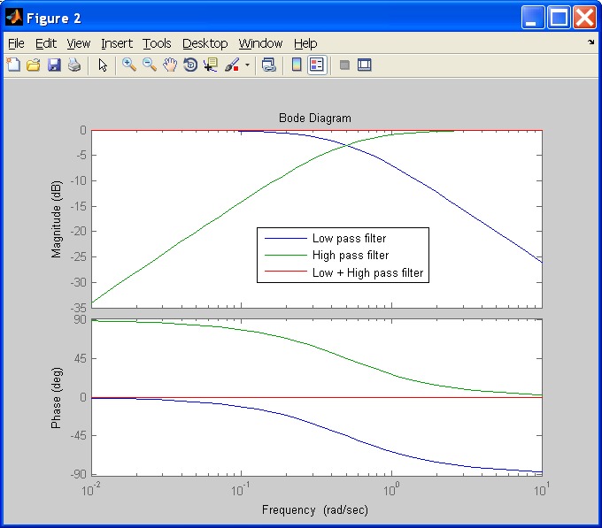
Bode diagram of a 0.08Hz 1st order complementary filter. The blue curve is the low pass filter. The green curve is the high pass filter and the red curve is the addition of both filters. The red curve has a phase of 0° and a gain of 1.
File history
Click on a date/time to view the file as it appeared at that time.
| Date/Time | Thumbnail | Dimensions | User | Comment | |
|---|---|---|---|---|---|
| current | 16:43, 20 August 2008 | | 680 × 597 (22 KB) | LubinKerhuel (talk | contribs) | Bode diagram of a 0.08Hz 1st order complementary filter. The blue curve is the low pass filter. The green curve is the high pass filter and the red curve is the addition of both filters. The red curve has a phase of 0° and a gain of 1. |
- You cannot overwrite this file.
File usage
The following page uses this file: