Blockset described on this wiki is deprecated since 2012.
For Model Based Design (MBD), use the free MPLAB Device Blocks for Simulink, tool from Microchip.
Updated Rapid Control Prototyping (RCP) custom projects are published at: https://lubin.kerhuel.eu.
Difference between revisions of "DsPIC Block/Digital Input"
Jump to navigation
Jump to search
(New page: The Digtal Input block reads the logical value previously writen on the microcontroller pin. =Dialog Box Parameters= ==Port== * Port used ==Pin== * Pin used, start at 0 and is defined i...) |
LubinKerhuel (talk | contribs) m (LubinKerhuel moved page Block/Digital Input to DsPIC Block/Digital Input: Block is a special page, creates many issues) |
||
| (5 intermediate revisions by the same user not shown) | |||
| Line 1: | Line 1: | ||
| − | The Digtal Input block reads the logical value | + | [[Image:Block_Digital_Input.png|thumb|rght|Block Digital Input]] |
| + | The Digtal Input block reads the logical value of the selected microcontroller pin. | ||
=Dialog Box Parameters= | =Dialog Box Parameters= | ||
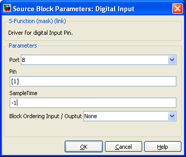
| − | + | [[Image:Block_DigitalInput_DialogBox.png|thumb|right|450px|Digital Input Dialog]] | |
==Port== | ==Port== | ||
* Port used | * Port used | ||
| Line 14: | Line 15: | ||
==Block Ordering Input / Output== | ==Block Ordering Input / Output== | ||
Create one input and/or output port on simulink. This port is virtual and do not add code in the microcontroller. It is used to force the execution order between two dsPIC/PIC24 peripheral blocks. (see examples) | Create one input and/or output port on simulink. This port is virtual and do not add code in the microcontroller. It is used to force the execution order between two dsPIC/PIC24 peripheral blocks. (see examples) | ||
| + | |||
| + | ---- | ||
| + | <comments \> | ||
Latest revision as of 19:30, 3 May 2015
The Digtal Input block reads the logical value of the selected microcontroller pin.
Dialog Box Parameters
Port
- Port used
Pin
- Pin used, start at 0 and is defined in vector form allowing several Pin to be read at the same time.
Sample Time
- -1 is inherited
Block Ordering Input / Output
Create one input and/or output port on simulink. This port is virtual and do not add code in the microcontroller. It is used to force the execution order between two dsPIC/PIC24 peripheral blocks. (see examples)
<comments \>

