FORUM TOPIC · READ ONLY
Output Compare block - Behaviour at edges values for OC1max
Output Compare block - Behaviour at edges values for OC1max
Forum : bug reports
5 message(s) · archive en lecture seule
I'm working on Output Compare block to make a PWM output and came across a strange
phenomena.
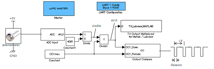
What I did was to connect a potentiometer to AN0 and a oscilloscope to OC1.
The potentiometer is hooked to +5V and GND.
I set MaxChannel of OC block to 1e-4, 2e-5,1e-5 to get 10kHz, 50kHz, 100kHz PWM signals.
Channels Input Type is set to be 10 to get variable Down duration.
When I turn the potentiometer in full swing, the PWM Down period varies between:
10kHz 500ns-100us
50kHz 500ns-20us
100kHz 500ns-10us.
OC1max value in each case is:
10kHz 3000
50kHz 600
100kHz 300.
What I think strange is that the pulse duration changes x2000, x400, x200 times.
These numbers should be the same as OC1max values, as they represent the maximum
allowable input to Output Capture block.
Why these difference happens? Is there any setting I miss?
Masaki
phenomena.
What I did was to connect a potentiometer to AN0 and a oscilloscope to OC1.
The potentiometer is hooked to +5V and GND.
I set MaxChannel of OC block to 1e-4, 2e-5,1e-5 to get 10kHz, 50kHz, 100kHz PWM signals.
Channels Input Type is set to be 10 to get variable Down duration.
When I turn the potentiometer in full swing, the PWM Down period varies between:
10kHz 500ns-100us
50kHz 500ns-20us
100kHz 500ns-10us.
OC1max value in each case is:
10kHz 3000
50kHz 600
100kHz 300.
What I think strange is that the pulse duration changes x2000, x400, x200 times.
These numbers should be the same as OC1max values, as they represent the maximum
allowable input to Output Capture block.
Why these difference happens? Is there any setting I miss?
Masaki
Re: OC1max value in Output Compare block
Hi Masaki,
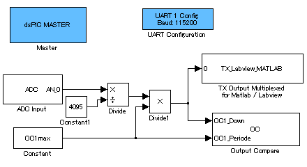
I upload the file I received by mail.
The pulse duration is the one defined in the block Output Compare dialog box. (If it is not the case, report it because it is a bug.)
The variable OC1max is a scalar value (uint16) that code for the max duration (max/channel) defined in the Output Compare dialog box.
This scalar value depends on the max duration (max/channel) set in the dialog box.
Few remarks about this model.
First, it is very useful to view data types.
In your case, I guess that after the first multiplication/division block, you get a double, and after the second multiplication block, you get a uint16 ?
I strongly advice to replace theses two multiplication blocks by one gain block with the value (OC1max/4095).
The output of this gain block should be a uint16.
The computation of the multiplication could be set to either uint16, or another more precise data type.
If you use only uint16 ; depending if OC1max/4095 is near an integer value or not consider using floor(OC1max/4095) to avoid higher result than OC1max. Example: OC1max/4095 = 2.7 ==> would be round to 3 if integer computation is chosen...
If I do not response to your question, please provide more details and upload the model.
I upload the file I received by mail.
Citation : Masaki What I think strange is that the pulse duration changes x2000, x400, x200 times.
These numbers should be the same as OC1max values, as they represent the maximum
Allowable input to Output Capture block.
The pulse duration is the one defined in the block Output Compare dialog box. (If it is not the case, report it because it is a bug.)
The variable OC1max is a scalar value (uint16) that code for the max duration (max/channel) defined in the Output Compare dialog box.
This scalar value depends on the max duration (max/channel) set in the dialog box.
Few remarks about this model.
First, it is very useful to view data types.
In your case, I guess that after the first multiplication/division block, you get a double, and after the second multiplication block, you get a uint16 ?
I strongly advice to replace theses two multiplication blocks by one gain block with the value (OC1max/4095).
The output of this gain block should be a uint16.
The computation of the multiplication could be set to either uint16, or another more precise data type.
If you use only uint16 ; depending if OC1max/4095 is near an integer value or not consider using floor(OC1max/4095) to avoid higher result than OC1max. Example: OC1max/4095 = 2.7 ==> would be round to 3 if integer computation is chosen...
If I do not response to your question, please provide more details and upload the model.
Re: OC1max value in Output Compare block
Masaki, I post the information from your mail here.
The Output Compare (OC) peripheral used as PWM output is not completely hardware driven. It means that a minimum time is required between two events : time for code execution. In your case of 33ns Down period (corresponding to 1/300
* 1/100000) the falling and rising edge are too close to each other. A minimum execution time for instruction being executed between two edges is necessary. In this case, from your data, this minimum time is about 500ns. This correspond to an input value for the OC block of 15. So, 15 is the minimum acceptable value for the Down input block. (the OC block act like as a saturation if you set value lower than 15).
Note that the same phenomena will appears as your input value get very close from the Periode (setting two edge very close)
If you require such a small down period, considere using a dsPIC with a motor PWM peripheral. The PWM peripheral is hardware driven and will work best on theses "edge" phenomena.
In each experiments, I set MaxChannel of OC block to 1e-4, 2e-5,1e-5 to get 10kHz, 50kHz, 100kHz PWM signals.
Channels Input Type is set to be 10 to get variable Down duration.
What I notice is that the ratio of min and max of Duration isn’t equal to OC1max in each frequency. For example, in case of 100kHz, min duration is 500nsec, max duration is 10usec. The ratio is 20, while OC1max is 300.
Does this make sense?
The Output Compare (OC) peripheral used as PWM output is not completely hardware driven. It means that a minimum time is required between two events : time for code execution. In your case of 33ns Down period (corresponding to 1/300
* 1/100000) the falling and rising edge are too close to each other. A minimum execution time for instruction being executed between two edges is necessary. In this case, from your data, this minimum time is about 500ns. This correspond to an input value for the OC block of 15. So, 15 is the minimum acceptable value for the Down input block. (the OC block act like as a saturation if you set value lower than 15).
Note that the same phenomena will appears as your input value get very close from the Periode (setting two edge very close)
If you require such a small down period, considere using a dsPIC with a motor PWM peripheral. The PWM peripheral is hardware driven and will work best on theses "edge" phenomena.
Re: Output Compare block - Behaviour at edges values for OC1max
I understand the situation.
As my CPU is dsPIC30F3013 at Fcy=30MHz, it's supposed to handle PWM signal generation by interrupts.
As a result, it can only generate edges at every 500ns at its fastest speed.
If I switch my CPU to dsPIC30F4012 with motor control pins,
does your software support hardware PWM signal generation?
As my CPU is dsPIC30F3013 at Fcy=30MHz, it's supposed to handle PWM signal generation by interrupts.
As a result, it can only generate edges at every 500ns at its fastest speed.
If I switch my CPU to dsPIC30F4012 with motor control pins,
does your software support hardware PWM signal generation?
Re: Output Compare block - Behaviour at edges values for OC1max
Citation : Masaki does your software support hardware PWM signal generation?
Yes, hardware PWM signal generation can be done using the "motor PWM peripheral"
Lubin