Blockset described on this wiki is deprecated since 2012.
For Model Based Design (MBD), use the free MPLAB Device Blocks for Simulink, tool from Microchip.
Updated Rapid Control Prototyping (RCP) custom projects are published at: https://lubin.kerhuel.eu.
Uncategorized files
Jump to navigation
Jump to search
Showing below up to 100 results in range #1 to #100.
View (previous 100 | next 100) (20 | 50 | 100 | 250 | 500)
 Block ADC.png 200 × 76; 719 bytes
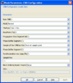
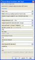 Block ADC DialogBox.png 365 × 621; 15 KB
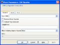 Block CANReceive TabGeneral DialogBox.png 442 × 333; 12 KB
 Block CANReceive TabRx0 DialogBox.png 442 × 333; 11 KB
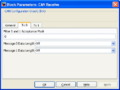
 Block CANReceive TabRx1 DialogBox.png 442 × 333; 12 KB
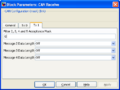
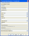
 Block CANTransmit DialogBox.png 442 × 537; 15 KB
 Block CAN Configuration.png 180 × 94; 777 bytes
 Block CAN Receive.png 180 × 87; 861 bytes
 Block CAN Transmit.png 180 × 87; 814 bytes
 Block CFunctionCall DialogBox.png 442 × 553; 13 KB
 Block C Function Call.png 200 × 61; 955 bytes
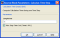 Block CalculusTimeStep DialogBox.png 365 × 233; 8 KB
 Block Calculus Time Step.png 108 × 59; 506 bytes
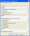
 Block CanConfig DialogBox.png 442 × 501; 16 KB
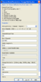 Block ChangeNotification DialogBox.png 365 × 716; 16 KB
 Block Change Notification.png 200 × 76; 1 KB
 Block Chronograph.png 200 × 61; 909 bytes
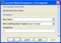 Block Chronograph DialogBox.png 360 × 259; 10 KB
 Block CompilerConfiguration DialogBox.png 442 × 177; 8 KB
 Block Compiler Configuration.png 150 × 78; 791 bytes
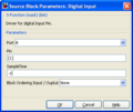 Block DigitalInput DialogBox.png 365 × 307; 9 KB
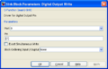
 Block DigitalOutputRead DialogBox.png 365 × 307; 10 KB
 Block DigitalOutputWrite DialogBox.png 442 × 285; 10 KB
 Block Digital Input.png 200 × 68; 826 bytes
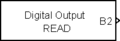 Block Digital OutputRead.png 200 × 68; 1,017 bytes
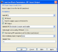
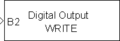 Block Digital OutputWrite.png 200 × 68; 954 bytes
 Block ExternalInterrupt DialogBox.png 365 × 581; 13 KB
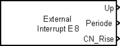 Block External Interrupt PWM.png 200 × 76; 1 KB
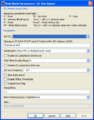 Block I2CMaster DialogBox.png 446 × 569; 17 KB
 Block IC2 Master.png 200 × 88; 950 bytes
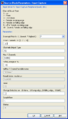 Block InputCapture DialogBox.png 401 × 701; 14 KB
 Block Input Capture.png 200 × 76; 1 KB
 Block Master.png 150 × 78; 695 bytes
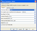 Block Master DialogBox.png 442 × 373; 19 KB
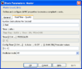 Block Master DialogBox Quartz.png 442 × 373; 15 KB
 Block NOP.png 200 × 61; 712 bytes
 Block Nop DialogBox.png 442 × 213; 8 KB
 Block OutputCompare DialogBox.png 444 × 519; 13 KB
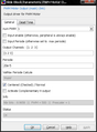
 Block OutputCompare DialogBox HW.png 642 × 718; 23 KB
 Block Output Compare.png 200 × 76; 932 bytes
 Block Output Compare HW.png 165 × 91; 3 KB
 Block PWMMotor DialogBox.png 436 × 592; 18 KB
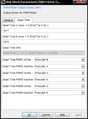 Block PWMMotor DialogBox DeadTime.png 436 × 592; 18 KB
 Block PWMMotor Illustration Centered.png 600 × 458; 42 KB
 Block PWMMotor Illustration DeadTime.png 600 × 251; 26 KB
 Block PWM Motor Output.png 200 × 76; 793 bytes
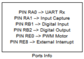 Block PortsInfo.png 184 × 129; 3 KB
 Block Reset DialogBox.png 442 × 134; 7 KB
 Block SPIConfig DialogBox.png 442 × 555; 17 KB
 Block SPIInputOutput DialogBox.png 442 × 397; 13 KB
 Block SPI Configuration.png 200 × 65; 832 bytes
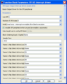 Block SPI IO InterruptDriven DialogBox.png 459 × 581; 22 KB
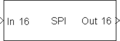 Block SPI Input Output.png 200 × 69; 809 bytes
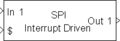 Block SPI Input Output InterruptDriven.png 200 × 69; 1 KB
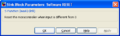
 Block Software Reset.png 200 × 63; 631 bytes
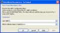
 Block UARTGeneral DialogBox.png 510 × 333; 14 KB
 Block UARTMultiplexed DialogBox.png 445 × 385; 13 KB
 Block UARTRxTab DialogBox.png 510 × 333; 14 KB
 Block UARTRx DialogBox.png 365 × 349; 10 KB
 Block UARTTxTab DialogBox.png 510 × 333; 14 KB
 Block UARTTx DialogBox.png 452 × 251; 10 KB
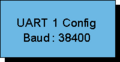 Block UART Configuration.png 200 × 104; 1 KB
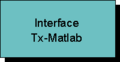 Block UART Interface TxMatlab.png 200 × 104; 1 KB
 Block UART Rx Input.png 150 × 66; 741 bytes
 Block UART Tx Output.png 150 × 66; 709 bytes
 Block UART Tx Output Multiplexed MatlabLabview.png 200 × 59; 782 bytes
 Block rs232gui DialogBox.png 842 × 269; 66 KB
 BlocksetLibrary.png 500 × 706; 15 KB
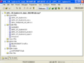
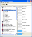 BlocksetLibraryBrowser.png 455 × 528; 21 KB
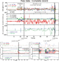 BlueToothDataLog Flight003.png 2,000 × 2,049; 107 KB
 Bluetooth logo.png 84 × 91; 1 KB
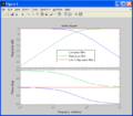 Bode 1stOrderComplementaryFilter.png 680 × 597; 22 KB
 CAN addedComponents.jpg 702 × 546; 54 KB
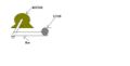 CaseStudy01 MotorDrawing.jpg 594 × 300; 9 KB
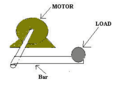 CaseStudy01 MotorDrawing.png 271 × 192; 5 KB
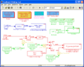
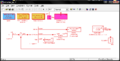 CaseStudy01 OriginalModel 01.png 929 × 474; 28 KB
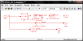 CaseStudy01 OriginalModel 02.png 712 × 348; 18 KB
 CaseStudy01 OriginalModel PID.png 480 × 226; 13 KB
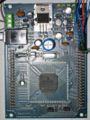
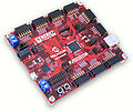 Cerebot32MX4-obl3-400.jpg 400 × 338; 46 KB
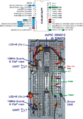
 Circuit CAN.png 717 × 1,221; 184 KB
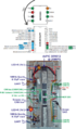
 Circuit PWM.png 1,000 × 1,436; 272 KB
 Circuit SPI.png 682 × 983; 182 KB
 CompilingSimulinkCodeWithMPLAB.png 640 × 480; 20 KB
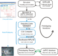 DevelopmentCycleWithBlockset.png 800 × 776; 183 KB
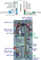
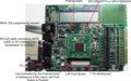 Explorer16Board.png 600 × 377; 104 KB
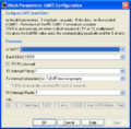
 Explorer16 ADCConfiguration.png 688 × 573; 16 KB
 Explorer16 DigitalInput.png 296 × 299; 11 KB
 Explorer16 DigitalOutput.png 324 × 264; 12 KB
 Explorer16 LoggedDataCurvesAnimation.gif 568 × 502; 148 KB
 Explorer16 LoggedDataCurvesStatics.png 568 × 502; 17 KB
 Explorer16 MasterBlockClock.png 424 × 480; 15 KB
 Explorer16 MasterBlockGeneral.png 424 × 480; 6 KB
 Explorer16 TxMatlabMultiplexed.png 421 × 421; 13 KB
 Explorer16 UARTConfiguration.png 420 × 412; 14 KB
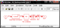
 Explorer16 rs232gui.png 604 × 187; 15 KB
 FlexBoard Blinking Led.mdl ; 45 KB
 FlexBoard Model BlinkingLed.png 710 × 566; 22 KB
 FlexBoard Photo.jpg 800 × 1,066; 296 KB
 FlexBoard ResultSinus.png 568 × 502; 16 KB
 FlexBoard ResultTimeStep.png 568 × 502; 15 KB


